brygga, bryggaCNC and CenteRail are trademarks of bryggaCNC, a California company.
bryggaCNC reserves the right to make modifications or substitutions without notice. See Terms and Conditions
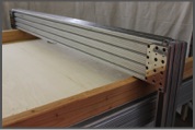
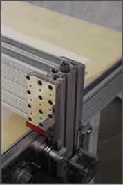
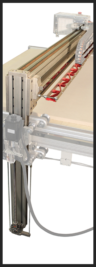
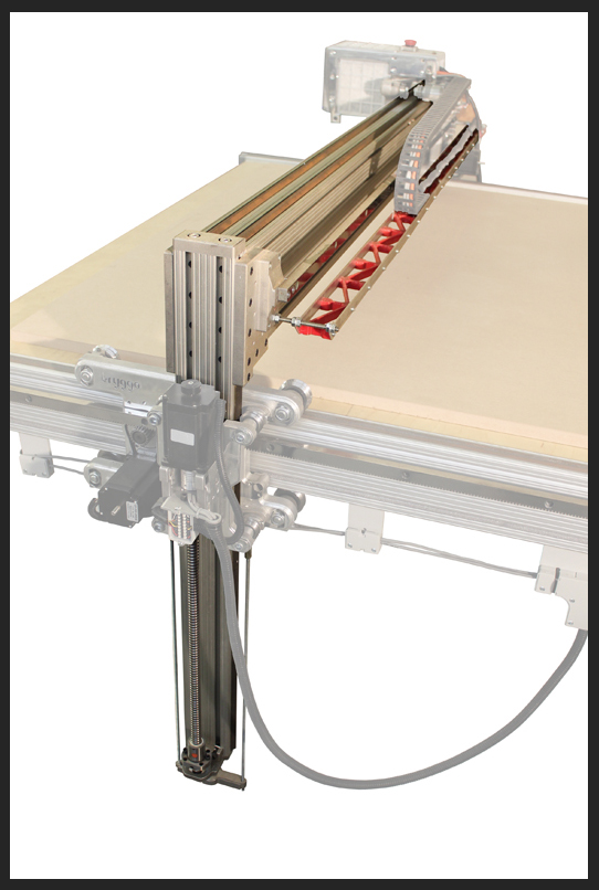
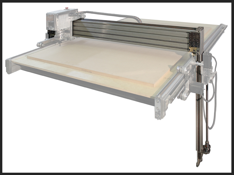
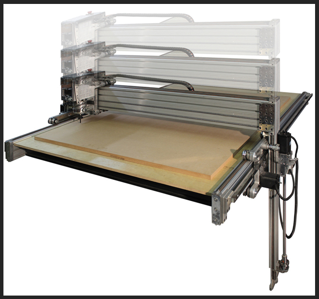
Z - axis and active gantry:
• Active gantry with linear motion in Z-axis.
• Fixed distance of spindle to the gantry beam.
• No conventional Z-axis slide or drop plate.
• Gantry weight balanced by spring suspension.
• Ball screw Z-axis linear motion drive at both ends.
• E-chain shelf.
• Gantry frame fully assembled and calibrated, ready to be placed on Y/A carriages.
• Spring suspension and ball screw systems require assembly.
• Polished aluminum faces as shown.
NOTE: Some images shown with optional brygga electronics set.
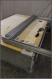
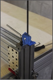
Placement and assembly of gantry on Y/A carriages
This task is the most tedious one and requires careful assembly.
You will need help for following steps. This is a 2+ person job!
Carefully place the gantry on the machine on some padding.
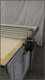
Turn the gantry around so that the risers clear the side rails and turn it upright. Some wood or padding will avoid scratches.
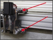
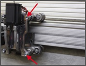
Loosen the two set screws on the Y carriage.
Do the same on the A carriage.
Loosen the two 3/8" bearing bolts on the Y carriage and push the bearings towards the rear of the machine.
Do the same on the A carriage.
CAUTION, THE GANTRY IS HEAVY!
All precautions like a support frame under the gantry or support straps above should be installed before attempting this step.
Lift the gantry with several helpers, keeping it upright and slide both sides carefully from the top in between the bearings.
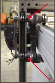
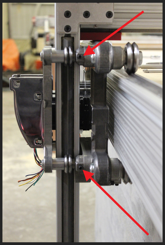
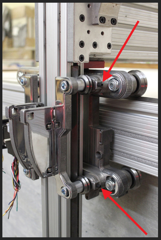
Once the gantry is in place, using the two set screws, tighten the pair of bearings on one side up against the rail using the same procedures as you did on the carriages.
Do the same tightening of bearings on the other side.
Following procedure is the most crucial adjustment!
With bearings tightened on both sides, carefully check to see if the bearings on both sides are perfectly aligned with the rails on the risers. Use a flashlight from the back to see if there are any gaps.
If the bearings are slightly in or out in relation to the rails, loosen the top two 3/8" bearing bolts on one side and add/remove shims behind the main bearing spacer to adjust. Tighten back on and check for gaps. Repeat until a good fit is achieved.
Repeat the same procedure on the bottom two bolts, adding/removing the same amount of shims. Retighten everything back on.
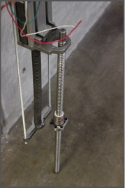
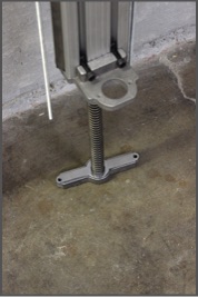
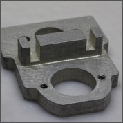
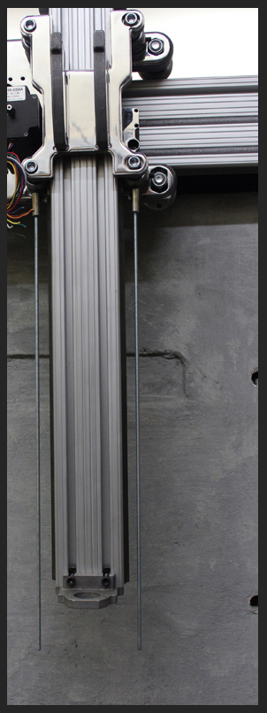
Assembly of spring suspension and bottom bracket:
Carefully remove the plastic bottom cover on one of the risers and discard.
Spring suspension set will slide down with it.
Push the white plastic liner into the recess of the bottom bracket. Spring and shaft will slide down through the bottom cap.
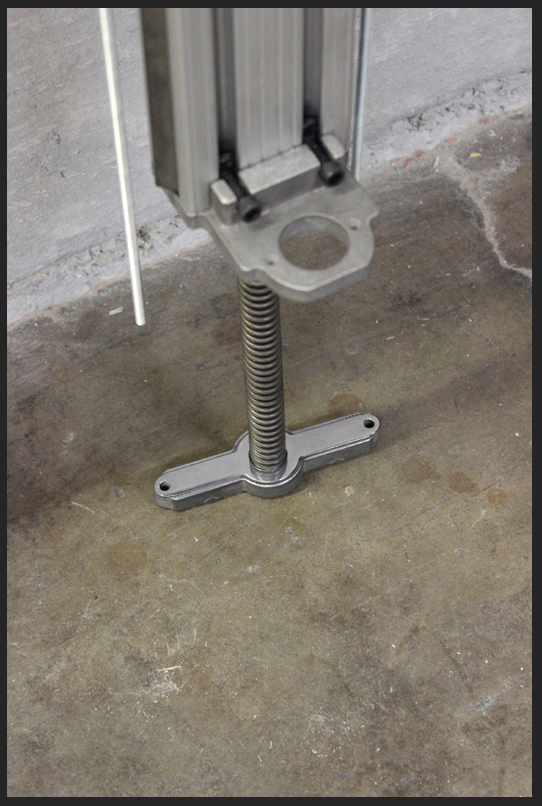
Screw down the aluminum bottom bracket to the riser from the front and the bottom.
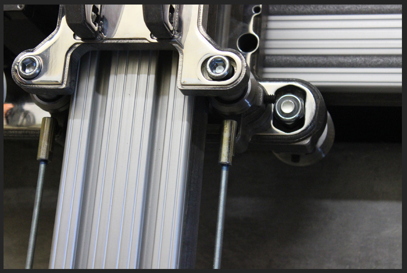
Install spring rod onto the bottom bar. Spring fits in a pocket on the bottom bar.
Install 10-32" threaded rods onto the ball joints. Use thread lock.
Lift bottom bar through the threaded rods and install nylock nuts.
Repeat procedure on the other side..
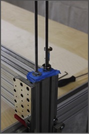
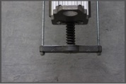
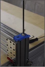
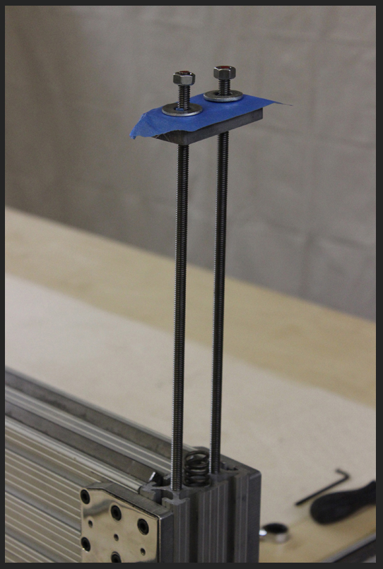
Pre-loading of spring suspension:
Remove riser top cap.
Install two 5/16" threaded rods until they bottom out.
Repeat on the other side.
Cover the riser top cap with protective tape and slip over the threaded rods. Install a washer and nut on each threaded rod.
Repeat on the other side.
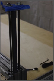
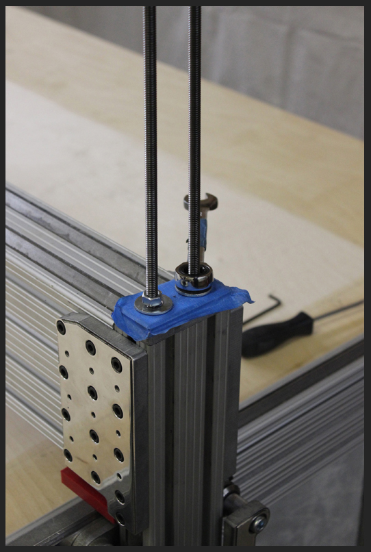
Take one of the plungers and push down the spring into the riser cavity.
Tuck the plunger under the cap.
Repeat on the other side.
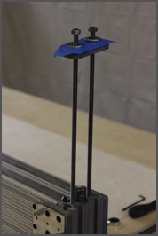
While holding the plunger in place, tighten down the nuts alternatingly on both sides until both caps with their plungers beneath are tigtened down at the same time.
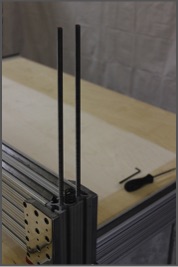
Remove one of the threaded rods and replace with a screw while the other rod stays tightened.
Once the screw is tight, remove the other rod and install the second screw.
Repeat the same on the other side.
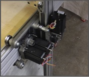
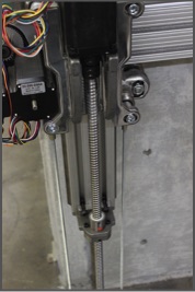
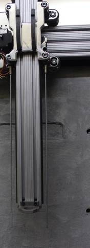
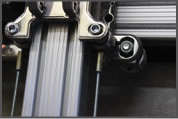
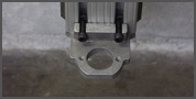
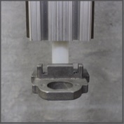
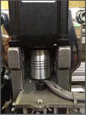
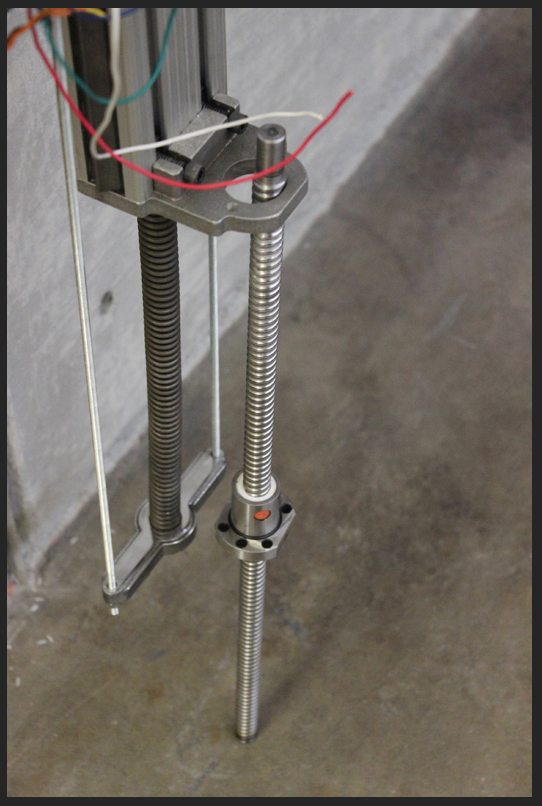
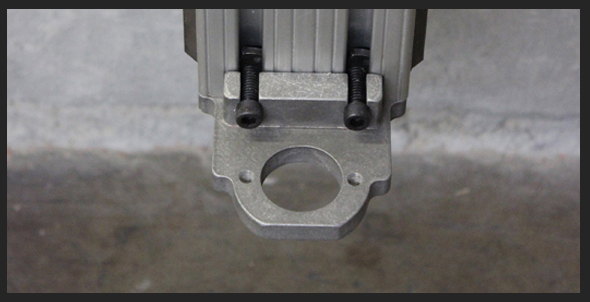
Ball nut assembly:
Place ball screw as shown.
Lift ball screw and attach ball nut to the bottom bracket from the bottom.
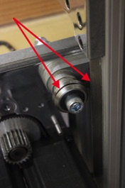
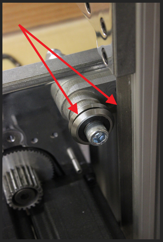
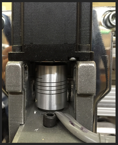
Loosen the stepper slightly so it can move on the shelf.
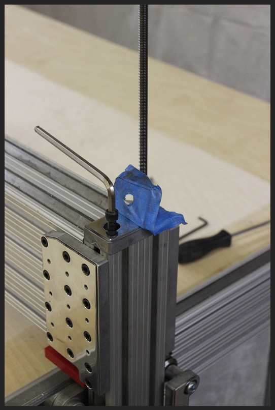
Loosen the bottom set screw on the coupler.
Place one thrust bearing on the step of the ball screw and turn the screw by hand so that it moves up through the mounting shelf and the upper thrust bearing.
Keep turning the ball screw by hand until it is inside the coupler.
Loosen the top set screw on the coupler holding the stepper shaft. Push down coupler with a screw driver while holding the ball screw so that the two thrust bearings are tightly sandwiched between the step on the ball screw and the bottom of the coupler without any play.
While holding tight, tighten the bottom set screw to lock everything in place.
Re-tighten the stepper to the shelf and the top set screw on the coupler to lock the stepper shaft to the coupler.
Designed and Manufactured in the USA
bryggaCNC - All rights reserved - Copyright 2016 - Centerail - Patent pending - Copyright 2016

> Z - Axis / Gantry